Disassembing, cleaning & repacking Outer CV Joints >>>
 03-27-2011, 01:24 PM
#1
AudiWorld Super User
Thread Starter
I have never found a reason to change an axle assembly on any of the many German cars I've owned and serviced. Only once had to replace a CV joint (77 Rabbit) and that was totally my fault. It literally took a couple thousand miles, with a ripped open boot, to finally start clicking then binding...no boot or grease left by that point.
These joints do NOT "contaminate" and fail that easily. A failed boot usually starts with a slit between the folds that expels grease all over your brakes, suspension and fender well. It's easy to spot the grease on the fender liner, if you're paying any attention to your car.
Unless you drive it in a Baja, Dakar or other dirt rally, it's not gonna suck in a bunch of abrasive and become irreparably damaged in a short time. I've let em go for weeks and still find unscored shiny ***** and races...even on a 200K mile VW that's been rebooted twice.
Many replace the entire axle with an aftermarket unit, when all that's wrong is a ripped boot. I don't even begin to get that, when all the hard work is getting the axle out and in...and I don't find doing the boot replacement with the axle still in the car easier or even an acceptable method. I think getting it all the way out of the car and locking it in a vice is much easier...and essential to cleaning, inspecting and repacking the joint properly.
An outer CV boot kit is $25 or less...including a new axle bolt, clamps, washer, spacer, c-clip and grease.
Anyway, with that editorial out of the way, I put together a little pictorial documenting how I disassemble, clean, inspect and repack my outer CV's.
I used the Bentley method to remove the axle (pinch bolt, upper control arms popped out of bearing housing, etc...) and the same with removal from and remounting to the shaft. The only extra step I take is removing the inner CV cast aluminum heat shield...lots more room to work axle out...worth the 3 extra bolts. The CV boot clamps can be "fun" to put on correctly...easy with the special "push-while-it-pinches" proper tool, which I used to borrow from a friend. Now I use an altered set of long handled wire cutters (not pictured), which had chipped cutting blades, so I ground the jaws into the proper angle and shape to pinch CV boot clamps tight. All those steps, including proper replacement of new dished washer, plastic spacer and c-clip on shaft, are up to you...It's all in the Bentley. This pictorial is all about the CV joint itself.
This is the only method I have ever used. It's the only way I feel assured that I've done a thorough inspection and maintenance...plus it's easy, for the most part requires no tools, only requires a couple of old rags and a few squirts of cheapo brake parts cleaner. Other methods require buckets full of solvent, offer no thorough inspection opportunity and run the real risk of leaving hidden contaminates in the joint...esp the type CV here.
WARNING: You may get dirty. If this is a problem, disregard this procedure and go with Raxles, as do others here...AND better yet pay someone else to do it for you...your manicure will remain clean and intact
I personally have no faith in aftermarket axle shafts' questionable construction/component quality (and esp cheaper brands...the prices are too suspicious for me) ...and more importantly, why throw out a perfectly operating, unfailed component???
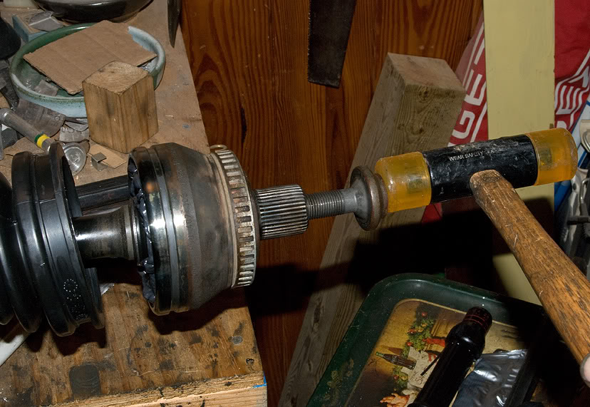
High tech method of CV removal...baby sledge and a railroad spike (a "drift" as Bentley calls it). Place firmly against a thick section of the the inner ball race...good firm whack and it's off. It only has to pop over a rounded edge c-clip on the end of the shaft. You can NOT hurt the inner race or shaft this way...it's actually still the Bentley method in their hard copy manuals for same year VW's which have the same CV joints. I've found that trying to remove them by using an axle bolt is extremely difficult and the torque required causes the shaft to rotate in the vice (and I use soft jaws).
CVjoint1.jpg?1301092043
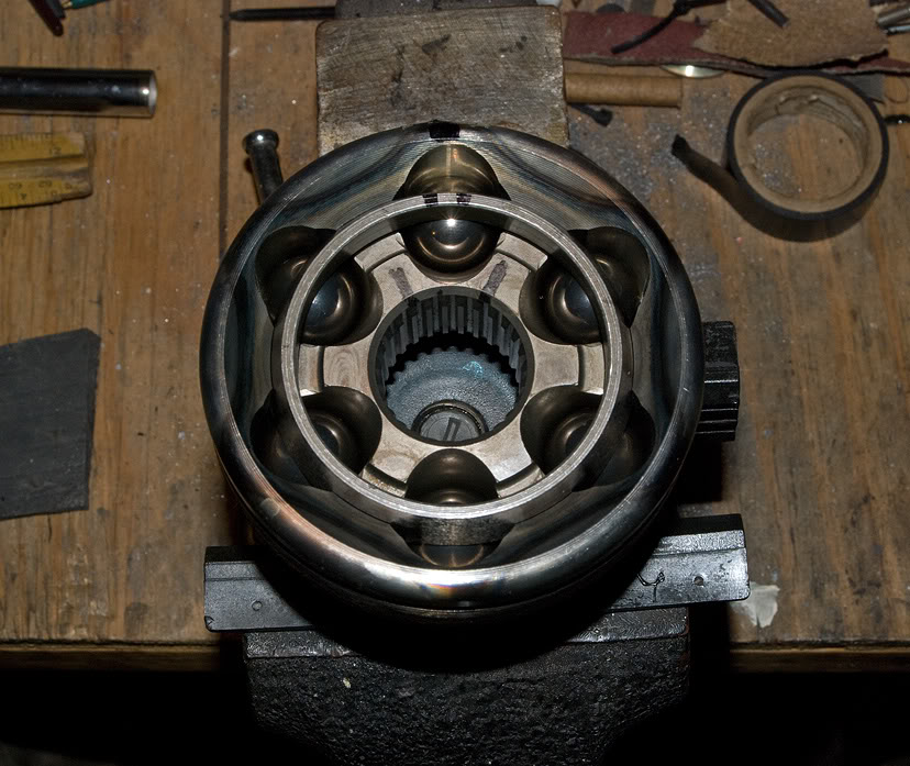
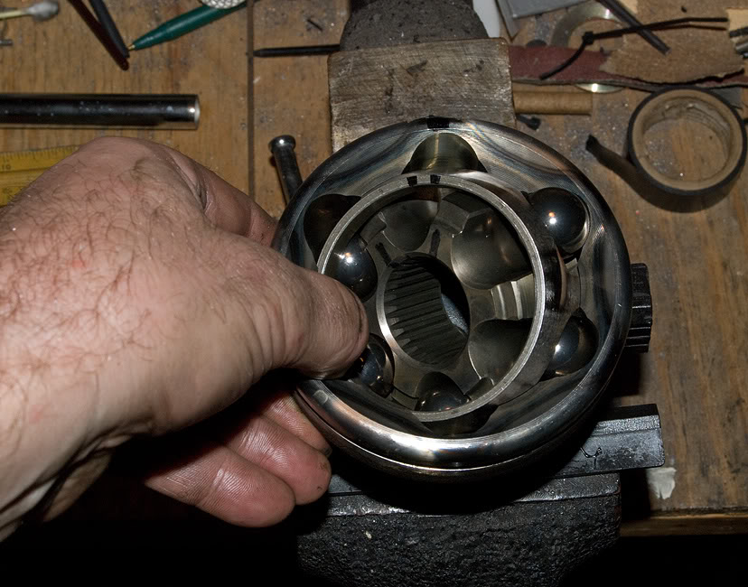
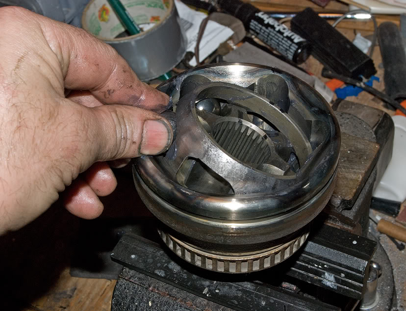
It's not a Rubik's cube...it's just a 6 hour Playskool clock...simple to disassemble with you fingers. Lock in a vice and mark the 12 o'clock position of outer race (joint), ball cage and inner race with permanent marker (Sharpie here....CAUTION: Permanent marker washes off with brake parts cleaner). This view is with all parts already cleaned for clarity.
CVjoint2.jpg?1301092105
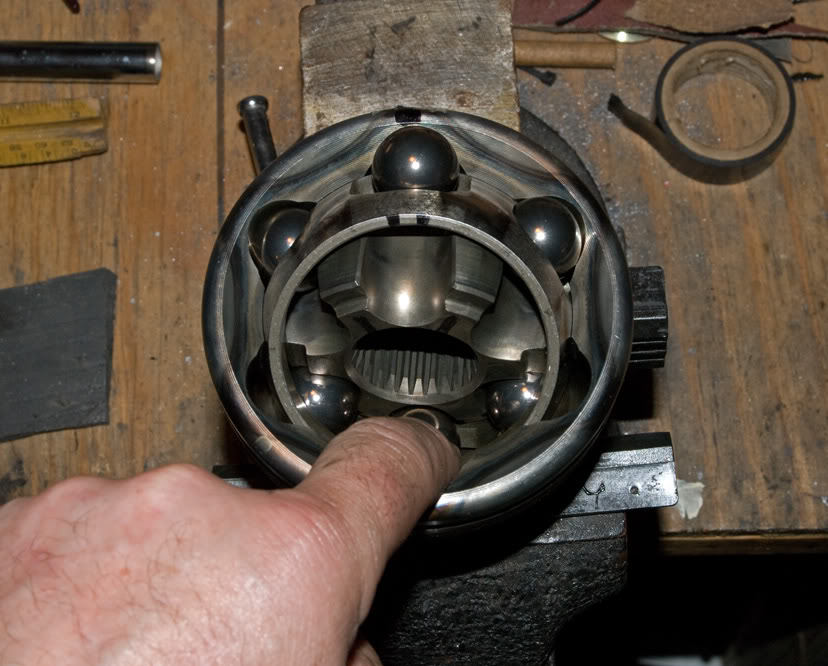
I've designated the 12 o'clock ball as #1 and continue through #6 in a clockwise direction. Start disassembly by pushing down inner race, cage and #4 ball simultaneously, which will lift ball #1 to removal position.
CVjoint3.jpg?1301092179
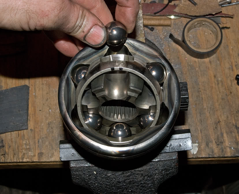
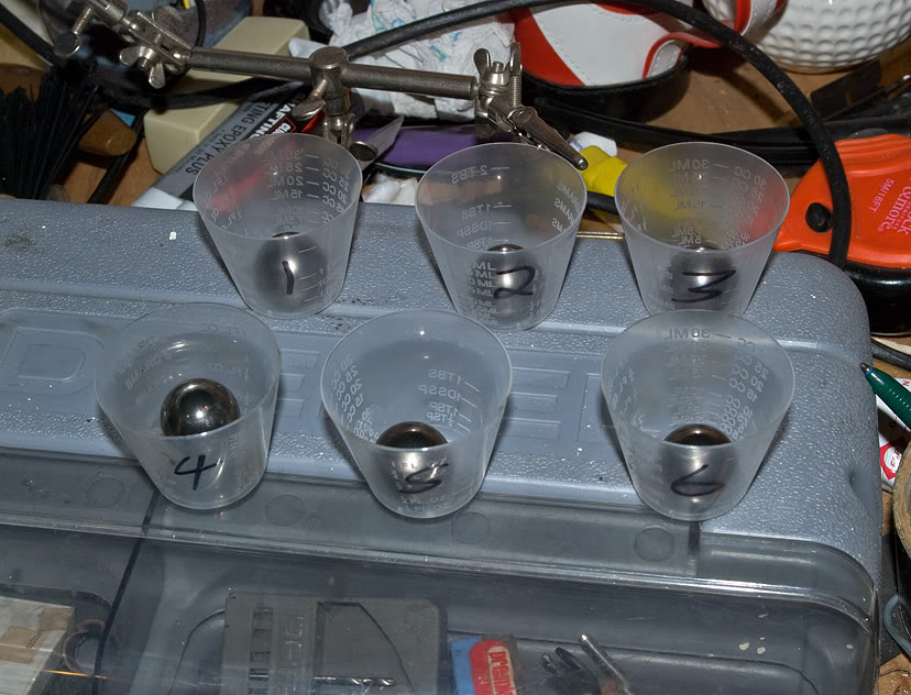
Remove number #1 ball and place it in a location labeled #1. I always return all parts, including each ball, to their exact original locations.
CVjoint4.jpg?1301092208
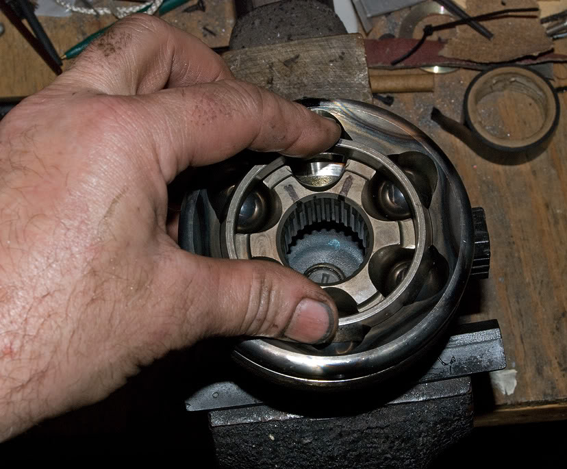
Return CV joint assembly to it's original flat configuration. I've found this assures free movement for the next ball removal. I recommend this step between every ball removal, to assure no binding of parts and no chance of any part falling out of place.
CVjoint5.jpg?1301092242
Next, going around the clock in order, press down inner race, cage and ball at #5 position to lift and free ball #2 for removal ...direct opposite side for every ball.
CVjoint6.jpg?1301092298
This is how I kept track of the *****, to assure being returned to correct positions upon reassembly. Why mess with what was working?
CVjoint7.jpg?t=1301092839
After having gone through each ball removal step, until #6 has been removed last, leaving ball cage flat, turn inner cage 90 degrees and work out carefully buy lining up it's protrusions with the cages open slots...doesn't matter how much you have turn it to find the free removal point, since it's correct position for replacement has been marked.
Note: Before removal, it's a good idea to assure proper position on the clock, by adding whatever it takes (plastic wires ties for instance) to assure that and top position...in case you don't have or washed away position marks.
CVjoint8.jpg?1301092337
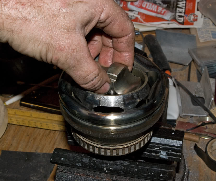
Pull the inner race free.
CVjoint9.jpg?1301092882
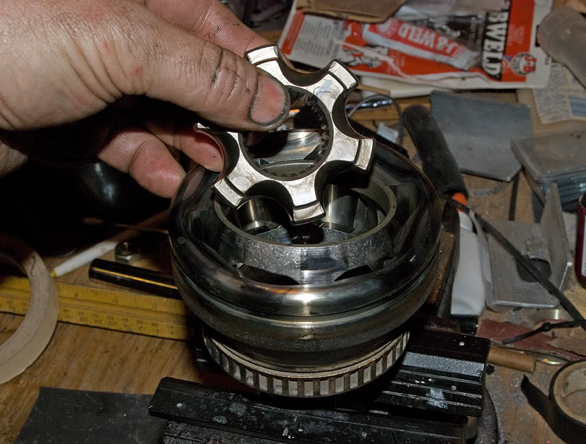
Do the same with ball cage...turn 90 degrees.
CVjoint10.jpg?1301092922
Work out with slots lined up with outer race protrusions to free it up and remove.
CVjoint11.jpg?1301092951
Notice wire tie on ball cage to keep track of 12 o'clock. I remark inner race and cage with Sharpie after a good cleaning.
CVjoint12.jpg?1301093004
Time for finger painting...lightly coat totally cleaned outer race with supplied grease.
CVjoint13.jpg?1301093037
Reassembly:
Grease coat and carefully work cage back in at 90 degrees, with slots over outer cage protrusion, however you need to turn it to drop into place, to position for no binding rotation.
Note: The grease alone will not erase the Sharpie marks.
CVjoint14.jpg?1301093083
Turn cage to flat position, correct (marked side up) to prepare for insertion of inner race.
CVjoint15.jpg?1301093136
Grease coat and work inner race in at 90 degrees, fitting protrusions into ball cage slots until it's in a position to rotate freely.
CVjoint16.jpg?1301093182
Flatten inner race, ball cage and rotate till all marks line back up to 12 o'clock (#1) position.
CVjoint17.jpg?1301093245
Press ball cage and inner race down at position #3, to facilitate inserting greased ball #6.
CVjoint18.jpg?1301093281
Again, flatten parts first.
CVjoint19.jpg?1301093304
Then press down ball cage and inner race at position #2 and insert greased ball #5. Continue the same around counterclockwise (reverse of disassemble), being sure to flatten cage and race between each ball insertion, to assure no binding smooth assembly.
CVjoint20.jpg?1301093333
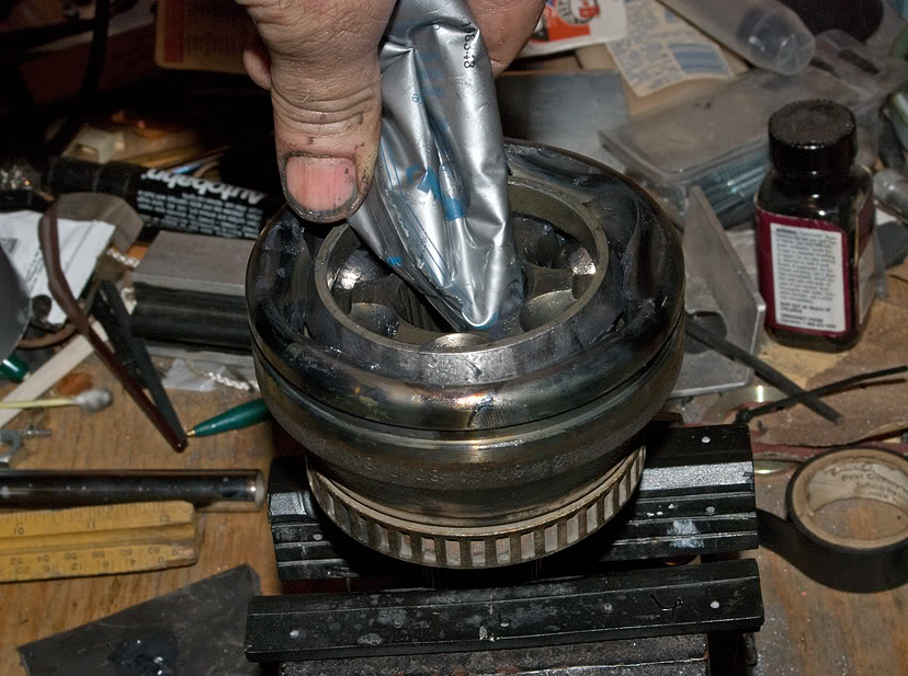
With axle bolt screwed in flush, to seal interior of CV joint while grease packing, squeeze as much as possible into the center.
CVjoint21.jpg?1301093365
Packing tool: 19mm deep well socket with electrical tape sealing one end.
CVjoint22.jpg?1301093393
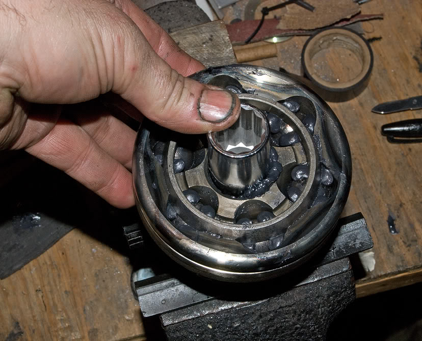
Press in grease, to make room for more. When all is in, it will pack the CV nicely from inside out. 80 gm pack will fit into joint alone (per Bentley).
CVjoint23.jpg?1301093441
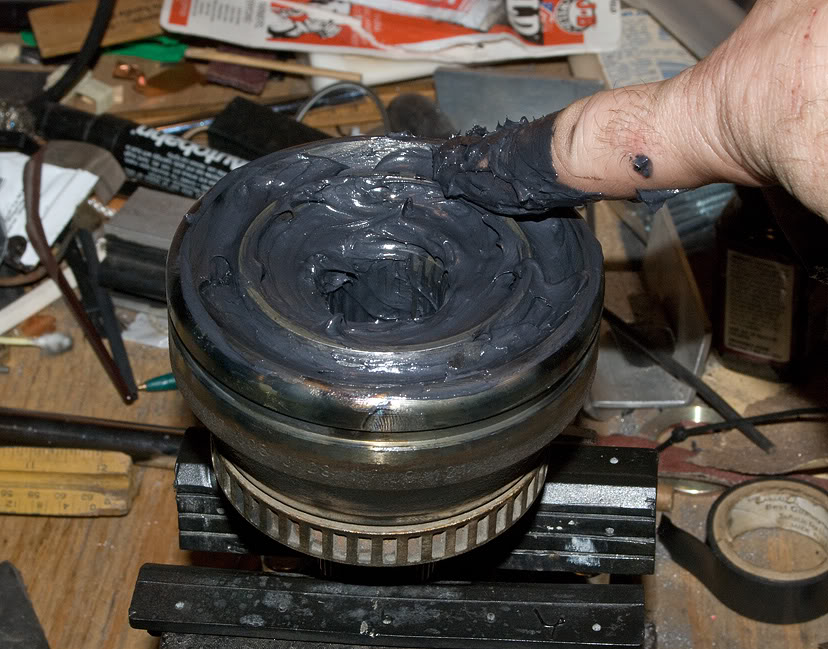
More fun than squarshin tadpoles ... "the iliad" by Ed Sanders 1969...Johnny ****-off...cult classic...anyone?
CVjoint24.jpg?1301093471
Slide joint back on and pop in place with a plastic/rubber hammer till it pops over the new c-clip on shaft...goes on easy compared to removal. Put another 40 gms (half remaining pack) of grease (per Bentley) in new boot before slipping it onto joint.
CVjoint25.jpg?1301093636
The rest is up to you. Enjoy.
These joints do NOT "contaminate" and fail that easily. A failed boot usually starts with a slit between the folds that expels grease all over your brakes, suspension and fender well. It's easy to spot the grease on the fender liner, if you're paying any attention to your car.
Unless you drive it in a Baja, Dakar or other dirt rally, it's not gonna suck in a bunch of abrasive and become irreparably damaged in a short time. I've let em go for weeks and still find unscored shiny ***** and races...even on a 200K mile VW that's been rebooted twice.
Many replace the entire axle with an aftermarket unit, when all that's wrong is a ripped boot. I don't even begin to get that, when all the hard work is getting the axle out and in...and I don't find doing the boot replacement with the axle still in the car easier or even an acceptable method. I think getting it all the way out of the car and locking it in a vice is much easier...and essential to cleaning, inspecting and repacking the joint properly.
An outer CV boot kit is $25 or less...including a new axle bolt, clamps, washer, spacer, c-clip and grease.
Anyway, with that editorial out of the way, I put together a little pictorial documenting how I disassemble, clean, inspect and repack my outer CV's.
I used the Bentley method to remove the axle (pinch bolt, upper control arms popped out of bearing housing, etc...) and the same with removal from and remounting to the shaft. The only extra step I take is removing the inner CV cast aluminum heat shield...lots more room to work axle out...worth the 3 extra bolts. The CV boot clamps can be "fun" to put on correctly...easy with the special "push-while-it-pinches" proper tool, which I used to borrow from a friend. Now I use an altered set of long handled wire cutters (not pictured), which had chipped cutting blades, so I ground the jaws into the proper angle and shape to pinch CV boot clamps tight. All those steps, including proper replacement of new dished washer, plastic spacer and c-clip on shaft, are up to you...It's all in the Bentley. This pictorial is all about the CV joint itself.
This is the only method I have ever used. It's the only way I feel assured that I've done a thorough inspection and maintenance...plus it's easy, for the most part requires no tools, only requires a couple of old rags and a few squirts of cheapo brake parts cleaner. Other methods require buckets full of solvent, offer no thorough inspection opportunity and run the real risk of leaving hidden contaminates in the joint...esp the type CV here.
WARNING: You may get dirty. If this is a problem, disregard this procedure and go with Raxles, as do others here...AND better yet pay someone else to do it for you...your manicure will remain clean and intact
I personally have no faith in aftermarket axle shafts' questionable construction/component quality (and esp cheaper brands...the prices are too suspicious for me) ...and more importantly, why throw out a perfectly operating, unfailed component???
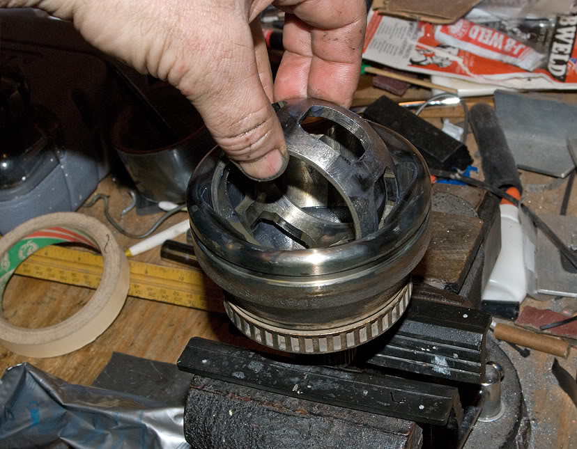
High tech method of CV removal...baby sledge and a railroad spike (a "drift" as Bentley calls it). Place firmly against a thick section of the the inner ball race...good firm whack and it's off. It only has to pop over a rounded edge c-clip on the end of the shaft. You can NOT hurt the inner race or shaft this way...it's actually still the Bentley method in their hard copy manuals for same year VW's which have the same CV joints. I've found that trying to remove them by using an axle bolt is extremely difficult and the torque required causes the shaft to rotate in the vice (and I use soft jaws).
CVjoint1.jpg?1301092043
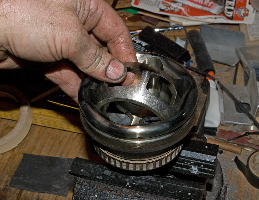
It's not a Rubik's cube...it's just a 6 hour Playskool clock...simple to disassemble with you fingers. Lock in a vice and mark the 12 o'clock position of outer race (joint), ball cage and inner race with permanent marker (Sharpie here....CAUTION: Permanent marker washes off with brake parts cleaner). This view is with all parts already cleaned for clarity.
CVjoint2.jpg?1301092105
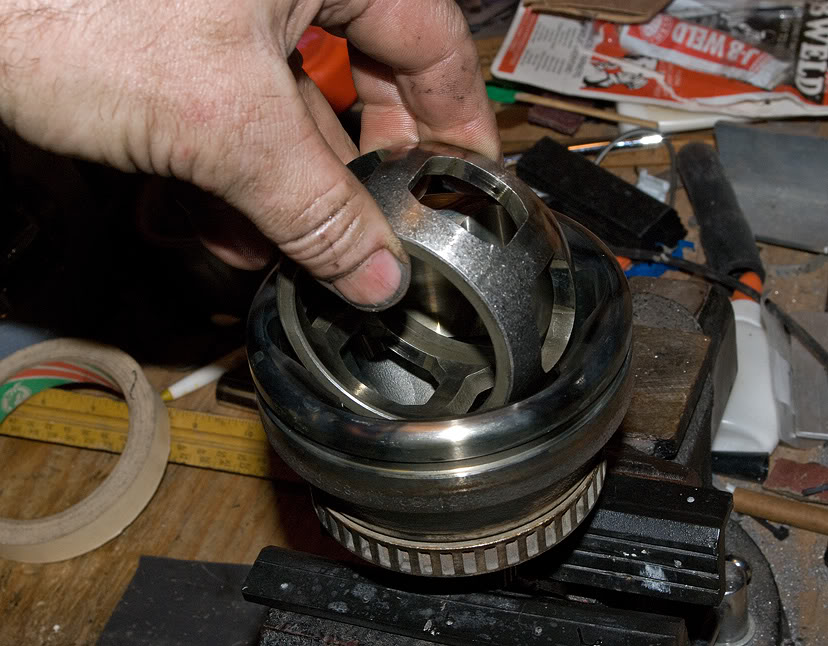
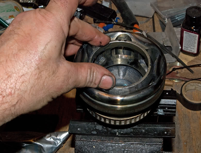
I've designated the 12 o'clock ball as #1 and continue through #6 in a clockwise direction. Start disassembly by pushing down inner race, cage and #4 ball simultaneously, which will lift ball #1 to removal position.
CVjoint3.jpg?1301092179
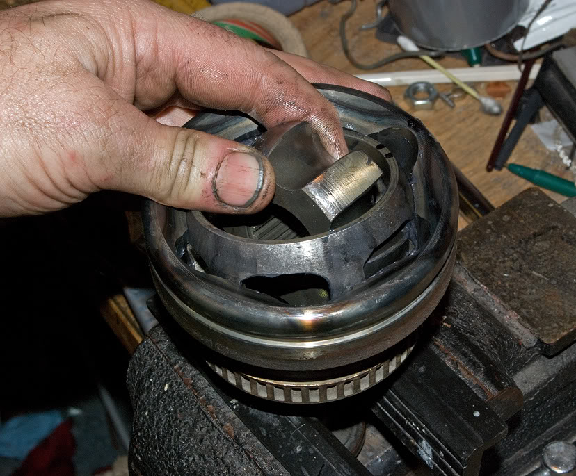
Remove number #1 ball and place it in a location labeled #1. I always return all parts, including each ball, to their exact original locations.
CVjoint4.jpg?1301092208
Return CV joint assembly to it's original flat configuration. I've found this assures free movement for the next ball removal. I recommend this step between every ball removal, to assure no binding of parts and no chance of any part falling out of place.
CVjoint5.jpg?1301092242
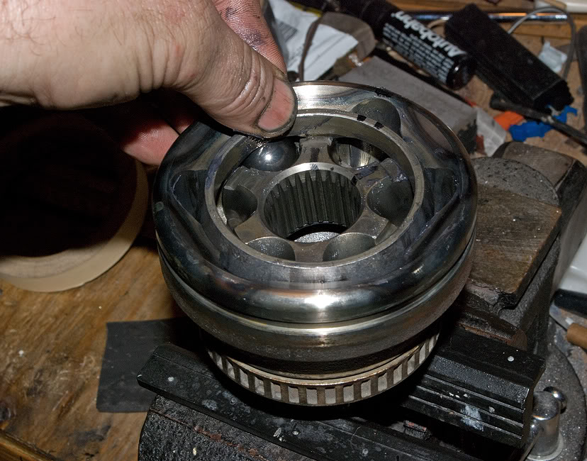
Next, going around the clock in order, press down inner race, cage and ball at #5 position to lift and free ball #2 for removal ...direct opposite side for every ball.
CVjoint6.jpg?1301092298
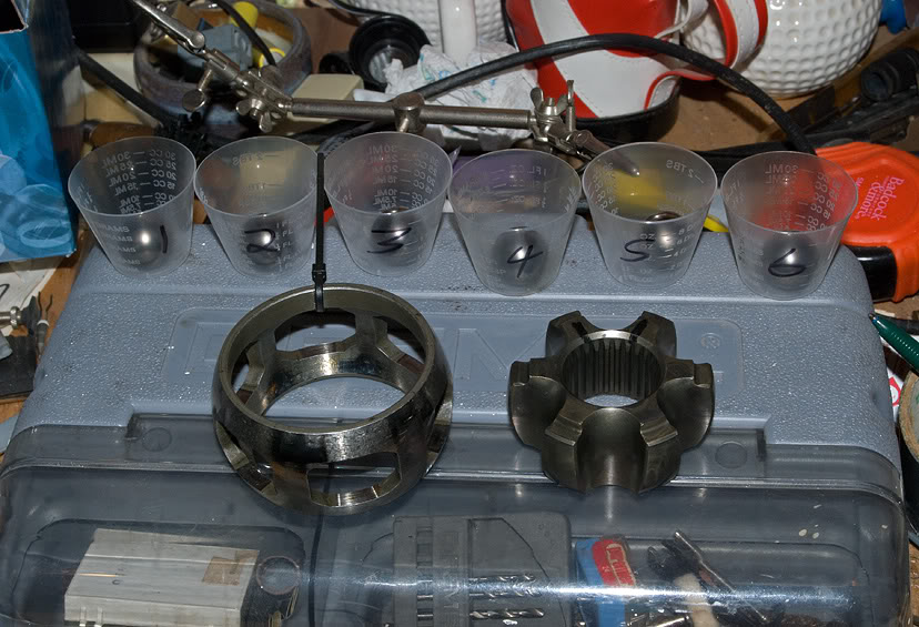
This is how I kept track of the *****, to assure being returned to correct positions upon reassembly. Why mess with what was working?
CVjoint7.jpg?t=1301092839
After having gone through each ball removal step, until #6 has been removed last, leaving ball cage flat, turn inner cage 90 degrees and work out carefully buy lining up it's protrusions with the cages open slots...doesn't matter how much you have turn it to find the free removal point, since it's correct position for replacement has been marked.
Note: Before removal, it's a good idea to assure proper position on the clock, by adding whatever it takes (plastic wires ties for instance) to assure that and top position...in case you don't have or washed away position marks.
CVjoint8.jpg?1301092337
Pull the inner race free.
CVjoint9.jpg?1301092882
Do the same with ball cage...turn 90 degrees.
CVjoint10.jpg?1301092922
Work out with slots lined up with outer race protrusions to free it up and remove.
CVjoint11.jpg?1301092951
Notice wire tie on ball cage to keep track of 12 o'clock. I remark inner race and cage with Sharpie after a good cleaning.
CVjoint12.jpg?1301093004
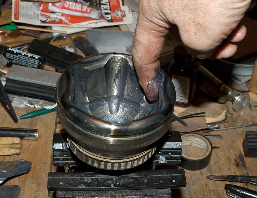
Time for finger painting...lightly coat totally cleaned outer race with supplied grease.
CVjoint13.jpg?1301093037
Reassembly:
Grease coat and carefully work cage back in at 90 degrees, with slots over outer cage protrusion, however you need to turn it to drop into place, to position for no binding rotation.
Note: The grease alone will not erase the Sharpie marks.
CVjoint14.jpg?1301093083
Turn cage to flat position, correct (marked side up) to prepare for insertion of inner race.
CVjoint15.jpg?1301093136
Grease coat and work inner race in at 90 degrees, fitting protrusions into ball cage slots until it's in a position to rotate freely.
CVjoint16.jpg?1301093182
Flatten inner race, ball cage and rotate till all marks line back up to 12 o'clock (#1) position.
CVjoint17.jpg?1301093245
Press ball cage and inner race down at position #3, to facilitate inserting greased ball #6.
CVjoint18.jpg?1301093281
Again, flatten parts first.
CVjoint19.jpg?1301093304
Then press down ball cage and inner race at position #2 and insert greased ball #5. Continue the same around counterclockwise (reverse of disassemble), being sure to flatten cage and race between each ball insertion, to assure no binding smooth assembly.
CVjoint20.jpg?1301093333
With axle bolt screwed in flush, to seal interior of CV joint while grease packing, squeeze as much as possible into the center.
CVjoint21.jpg?1301093365
Packing tool: 19mm deep well socket with electrical tape sealing one end.
CVjoint22.jpg?1301093393
Press in grease, to make room for more. When all is in, it will pack the CV nicely from inside out. 80 gm pack will fit into joint alone (per Bentley).
CVjoint23.jpg?1301093441
More fun than squarshin tadpoles
... "the iliad" by Ed Sanders 1969...Johnny ****-off...cult classic...anyone? CVjoint24.jpg?1301093471
Slide joint back on and pop in place with a plastic/rubber hammer till it pops over the new c-clip on shaft...goes on easy compared to removal. Put another 40 gms (half remaining pack) of grease (per Bentley) in new boot before slipping it onto joint.
CVjoint25.jpg?1301093636
The rest is up to you. Enjoy.
 03-13-2018, 06:14 PM
#2
AudiWorld Newcomer

Join Date: Mar 2018
Posts: 1
Likes: 0
Received 0 Likes
on
0 Posts

Bevelled surface on end of cage

Flat surface on end of cage
It's not a Rubik's cube...it's just a 6 hour Playskool clock...simple to disassemble with you fingers. Lock in a vice and mark the 12 o'clock position of outer race (joint), ball cage and inner race with permanent marker (Sharpie here....CAUTION: Permanent marker washes off with brake parts cleaner). This view is with all parts already cleaned for clarity.
Attachment 79544
I've designated the 12 o'clock ball as #1 and continue through #6 in a clockwise direction. Start disassembly by pushing down inner race, cage and #4 ball simultaneously, which will lift ball #1 to removal position.
After having gone through each ball removal step, until #6 has been removed last, leaving ball cage flat, turn inner cage 90 degrees and work out carefully buy lining up it's protrusions with the cages open slots...doesn't matter how much you have turn it to find the free removal point, since it's correct position for replacement has been marked.
Note: Before removal, it's a good idea to assure proper position on the clock, by adding whatever it takes (plastic wires ties for instance) to assure that and top position...in case you don't have or washed away position marks.
The rest is up to you. Enjoy.
I have looked on line and found many photos, but there does not seem to be any comsistency there.
I have called several VW shops and no-one knows which way it goes.
Any advice on this would be very much appreciated.
Cheers
Jan

Thread
Thread Starter
Forum
Replies
Last Post
Worldwidebeagle
Audi allroad
1
10-17-2013 12:16 PM
Regenmeister
Audi 90 / 80 / Coupe quattro / Cabriolet
2
09-18-2006 11:40 AM

