Frequently Asked Questions (FAQ), Procedures and Resources


 12-26-2006, 01:09 AM
#12
AudiWorld Member

Join Date: May 2005
Posts: 272
Likes: 0
Received 0 Likes
on
0 Posts
Another Useless Deutch Invention
Affectionately Used During Icestorms
Always Unusual Designs Incorperated.
Always Uncertain Door Ingress
Always Unanimous Doing It
Another Unlimited Driving Icon
Always Unorthodox Design Implementations
Awesomely Underrated Driving Icon
Always Under De Influence
Always Usurping Driver Income
Always Under Diagnostic Investigation
Always Underestimated Driving Instrument
Accelerates Under Demonic Influence
Automobile Underwater, Driver Insane
Attention: Unhappy Demons Irked
Already Umpteen Doorhandles Installed (or All ... Inoperative)
Appropriate Underground Destination Interface (only when "turbo" is rebadged "diesel")
Alienated Urban Drivers Intoxicated
Atrocious Useless Details Ignored
Approximately Universal Directional Indicator
Accelerator Under Dashboard Installation (think I'd better quit while I'm behind)<ul><li><a href="http://www.urbandictionary.com/define.php?term=audi">slangish</a></li></ul>
12-26-2006, 02:23 AM
#13
AudiWorld Member
Join Date: May 2005
Posts: 272
Likes: 0
Received 0 Likes
on
0 Posts
"I hope that I will soon forget the Audi Quattro. Until I do, I shall continue to worship that bitch goddess Success at the expense of friends, family, honesty and decency - anything to be in a position to have one. The Quattro is evil, an insidious witch in the guise of state-of-the-art engineering, a circe who commands your obedience every waking moment and a succubus who haunts every dream. She's the seductress who recreates That First Time all over again, who snips all your tethers to innocence and changes your life forever." - Four Wheeler Magazine, August 1982
12-26-2006, 03:35 AM
#14
AudiWorld Super User

Thread Starter
The Cam Position Sensor is used by the ECU (Engine Control Unit, i.e. the Motronic Computer) to figure out where the pistons are early in the starting cycle rather than waiting for the crank position sensor to come around. If the ECU does not get a cam position sensor signal, it will not fire the fuel pump relay. Once the engine is running, the ECU will use the crank sensor position sensor to keep track of things. If the cam sensor fails, a "2113" blink code will be thrown (into memory) and check engine light will come on. If it fails while running, you can keep driving but as soon as you turn the engine off, you are done. The engine will NOT re-fire until you fix the cam sensor. Location photo and diagrams in the URL links below.
12-26-2006, 03:36 AM
#15
AudiWorld Super User
Thread Starter
<ul><li><a href="https://forums.audiworld.com/s4s6/msgs/101711.phtml">https://forums.audiworld.com/s4s6/msgs/101711.phtml</a</li></ul>
12-26-2006, 03:39 AM
#16
AudiWorld Super User
Thread Starter
<ul><li><a href="https://forums.audiworld.com/s4s6/msgs/126842.phtml">https://forums.audiworld.com/s4s6/msgs/126842.phtml</a</li></ul>
12-26-2006, 04:04 AM
#17
AudiWorld Super User
Thread Starter
The ECU controls the fuel pump (FP) relay (J17)(PN 4D0 951 253) (located under the driver's side (LHD) knee bolster, right end of relay panel). The ECU will not engage the J17 until it has a signal from the cam position sensor (G40) during start-up and then the engine speed sensor (G28) during running. However, the FP relay does more than that.
Update: April 4/09: 4D0 951 253 which was the 208 relay is now superceded by 4D0 951 253B, the 372 relay. KATE's verbiage is:
"contact close relay for fuel pump
relay location/code no.: 6/372
to be used for code no.: 208"
Follow the URL for more info as to why the J17 is SO important.<ul><li><a href="https://forums.audiworld.com/s4s6/msgs/133907.phtml">https://forums.audiworld.com/s4s6/msgs/133907.phtml</a</li></ul>
Last edited by UrS4boy; 04-04-2009 at 08:49 AM.
12-26-2006, 04:12 AM
#18
AudiWorld Super User
Thread Starter
This should help if you are trying to track down a problem (electrical pun intended). You will still need a wiring diagram from the Bentley:
Pin-Out for the AAN ECU (or Engine Control Module (ECM)) T55 connector
The AAN ECU connector has 55 pin positions. The pins are arranged in three rows. The longest row has 19 pins, Pins 1 through 19. Pin 1 is nearest the metal release lever on the harness connector. The middle row is Pins 20 through 37, with Pin 20 nearest the metal release lever. The last row is Pins 38 through 55 with Pin 38 nearest the metal release lever. Not all pins are used.
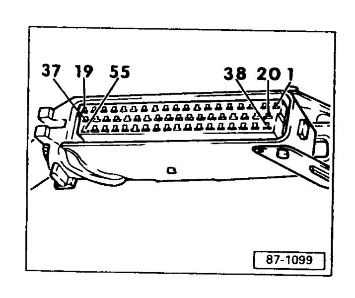
The following are the Pins and their assignment. The information is taken from the Robert Bentley manual with comments based on VAG service manual 143 (VAG143) information and some experience.
The Letter/Number, e.g. N71, are for the devices that are either being controlled or are sending a signal to the ECU. The Letter/Letter code is the wire colour code. Not all pins are used - especially on the standard transmission cars.
Wire Colour Codes used in the pin-out list below:
BK = Black
BL = blue
BR = Brown
CL = Clear
G = green
GY = gray
LT G = Light green
OR = orange
R= red
V = Violet
W = white
Y = Yellow
Examples:
W/V = white with a violet stripe
R/BK = red with a black stripe
Pin - Assignment - Device Code - wire colour - Comment (if any)
1/55 - Output to Power Output Stage - N122- G/W- for Coil No. 1 (N122 Pin 4/4)
2/55 - Output to Power Output Stage - N122 - V/BK - for Coil No. 2 (N122 Pin 3/4)
3/55 - Output to Fuel Pump Relay - J17 - BR/Y - ECU triggers the relay after it gets the G40 cam position sensor signal
4/55 - Idle Air Control Valve (aka Idle Stabilization Valve (ISV)) - N71 - W/Y the ISV is used to control the idle, e.g. when the air conditioning compressor comes on.
5/55 - Output (Fuel) Tank Breather valve N80 - W/R- Controls the evaporative emissions frequency valve - N80 - to cycle evaporated fuel vapours back in to the engine (NOTE: Bentley shows this as T55/3 on page X57 - presumably in error) VAG143 has it as N80.
6/55-Connection to A/C Control Head -E87- G/Y - Used to shut off A/C for up to 12 seconds when throttle is opened rapidly at speeds under 7 kph and shut off A/C for up to 3 seconds when in first gear and throttle position is at 65 degrees or more (full load) Ref: VAG143.
7/55-Mass Air Flow (MAF) Sensor - G70 - G/W - the MAF allows the ECU to know how much air (by mass) is heading to the cylinders so it can adjust the fuel, boost and timing to suit the conditions
8/55- Input from Hall Sender - G40 - GY/R - signal wire - Not lack of signal = Blink code 2113 and the engine will not start
9/55 - Barometric sensor - G16 - GY/BK - provides a signal to the ECU to help control boost at higher altitudes - between 1000 and 4000 meters - prevents the turbo from spinning over 155000 rpm.
10/55- Ground for Lambda (Oxygen) Sensor - G39-BR/R
11/55 -Input from Knock Sensor No. 1 - G61- G/G - for cylinders No. 1, 2 and 3
12/55- Power Supply (+5V) out to Hall sender - G40; Throttle Potentiomenter (G69) and Altitude Sensor (F96) - R/R -
13/55- Output to Data Link connector "L" for diagnostics - W/R
14/55-Ground for Fuel Injectors (N30-83)- BR/W - ground on intake manifold
15/55-Not Used
16/55 - Output control signal to Fuel Injector No. 5 - N83 - W/BL
17/55- Output control signal to Fuel Injector No. 2 - N31 - W/BR
18/55- Constant power supply to ECU J220 - R/R- from power terminal 30 (+12V) Fuse S26 (5A) - passenger footwell
19/55- Ground from the ECU for various ECU controlled devices - BR/R - to intake manifold
20/55 - Output to Power Output Stage - N127 - BK/Y - for Coil No. 4 (Note - some early versions of the Bentley have this as Coil No. 5 - but this is wrong, it is 4 - check it yourself) - VAG143 has it correct.(N127 connector Pin 4/4)
21/55 - Output to Power Output Stage - N127 - BK/W - for Coil No. 5 (Note - some early versions of the Bentley have this as Coil No. 4 - but this is wrong, it is 5 - check it yourself)- VAG143 has it correct. (N127 connector Pin 3/4)
22/55 - Data Link Connector - W/BL - linked to Check engine light (Malfunction indicator lamp) - also used in the blink code check.
23/55 - Output to Power Output Stage - N122- BK/GY signal for Cyl #3 Ignition coil (N122 connector Pin 1/4)
24/55- Power Ground for "actuators" other than injectors - Not found in Bentley, presume BR/R, ground to intake manifold
25/55- Mass Air Flow (MAF) Sensor (aka - hot-wire air volume meter) - G70 - G/V- Burn off signal from ECU - every time the engine is switched off, the hot wire is heated to 1000 deg C for one second to keep it clean
26/55- MAF - G70 - R/BK- "Reference voltage, earth (ground) in"
27/55- Switched Power to ECU from power (+12V) - BK/G - from Terminal 15 under the knee bolster - 15A circuit breaker, BK in BK/G out - S64
28/55- Heated Oxygen (O2) Sensor - G39- G/G- input from sensor
29/55-Input from Knock Sensor No. 2 - G66 - W/W- for cylinders No. 4 and 5
30/55- Ground for ECU and ECU sensors - G/BK
31/55- Fuel consumption signal for trip computer - BL/BK - Note: only used in N.America on 92 spec cars
32/55-Output toTrip Computer Boost Pressure Gauge - Y/BL - Note: only used in N.America on 92 spec cars
33/55 - Waste Gate Frequency Valve - N75 - Y/R - also know as the charge pressure control actuating valve - lets the ECU control the boost - by dumping excess boost through the waste gate
34/55 - Output control signal to Fuel Injector No. 3 - N32 - Y/BL
35/55 - Output control signal to Fuel Injector No. 4 - N33 - Y/G
36/55 - Output control signal to Fuel Injector No. 1 - N30 - W/V
37/55-Switched +12V for all 5 Fuel injectors (N30-N83) and MAF (G70)- BK/R - 15A - Circuit Breaker S72
38/55-T6ag Coding plug -Pin 1-GY/W
39/55-T6ag Coding plug- Pin 2- GY/Y
40/55-Input from Engine Speed Sensor - G28 - V/BK - Also connected to Ch.28 in the A/C head (you can read out RPM in the A/C head)
41/55-Signal from A/C control module -W/W - signal used by ECU to increase idle speed through ISV control when A/C compressor is activated (actually just maintains the idle speed when the extra load from A/C compressor is added to the system during idle)
42/55 -Gear selection input - Automatic only
43/55 - Not used
44/55 - Intake Air Temperature (IAT) Sensor - G42 - BR/BL - the ECU uses this signal to dial back timing (and power) to prevent pinging if the intake air temp is too high
45/55 - Engine Coolant Temperature Sensor - G62 - GY/BR - the one at the back of the head that the AAN ECU uses to figure out if the A/F should be enriched because the engine is cold.
46/55- Not used
47/55- Input from Crankshaft Position Sensor - G4 - V/V - used by the ECU to control ignition and fuel injector timing
48/55- Combined ground through ECU for G4 crankshaft position sensor and the G28 engine speed sensor - R wire from G4 and BL wire from G28
49/55-Input from Engine Speed sensor - G28 - GY/GY
50/55- Road Speed signal output (input?) to Instrument Cluster-G21-W/BL-signal also goes to Automatic Climate Control Head Channel 17 - which you can read out speed as well.
51/55- Not used for standard transmission cars - relates to shift point for automatic trans cars
52/55 - Idle Switch - F60 V/V- a microswitch inside the G69 throttle potentiometer that tells the ECU that the throttle is closed
53/55 - Throttle valve potentiometer - G69 - GY/GY the potentiometer on the throttle body that tells the ECU the degree to which the throttle body is open
54/55- Not used for standard transmission cars - relates to automatic trans cars
55/55- Output to Data Link connector "K" for diagnostics - G/R
Pin-Out for the AAN ECU (or Engine Control Module (ECM)) T55 connector
The AAN ECU connector has 55 pin positions. The pins are arranged in three rows. The longest row has 19 pins, Pins 1 through 19. Pin 1 is nearest the metal release lever on the harness connector. The middle row is Pins 20 through 37, with Pin 20 nearest the metal release lever. The last row is Pins 38 through 55 with Pin 38 nearest the metal release lever. Not all pins are used.
The following are the Pins and their assignment. The information is taken from the Robert Bentley manual with comments based on VAG service manual 143 (VAG143) information and some experience.
The Letter/Number, e.g. N71, are for the devices that are either being controlled or are sending a signal to the ECU. The Letter/Letter code is the wire colour code. Not all pins are used - especially on the standard transmission cars.
Wire Colour Codes used in the pin-out list below:
BK = Black
BL = blue
BR = Brown
CL = Clear
G = green
GY = gray
LT G = Light green
OR = orange
R= red
V = Violet
W = white
Y = Yellow
Examples:
W/V = white with a violet stripe
R/BK = red with a black stripe
Pin - Assignment - Device Code - wire colour - Comment (if any)
1/55 - Output to Power Output Stage - N122- G/W- for Coil No. 1 (N122 Pin 4/4)
2/55 - Output to Power Output Stage - N122 - V/BK - for Coil No. 2 (N122 Pin 3/4)
3/55 - Output to Fuel Pump Relay - J17 - BR/Y - ECU triggers the relay after it gets the G40 cam position sensor signal
4/55 - Idle Air Control Valve (aka Idle Stabilization Valve (ISV)) - N71 - W/Y the ISV is used to control the idle, e.g. when the air conditioning compressor comes on.
5/55 - Output (Fuel) Tank Breather valve N80 - W/R- Controls the evaporative emissions frequency valve - N80 - to cycle evaporated fuel vapours back in to the engine (NOTE: Bentley shows this as T55/3 on page X57 - presumably in error) VAG143 has it as N80.
6/55-Connection to A/C Control Head -E87- G/Y - Used to shut off A/C for up to 12 seconds when throttle is opened rapidly at speeds under 7 kph and shut off A/C for up to 3 seconds when in first gear and throttle position is at 65 degrees or more (full load) Ref: VAG143.
7/55-Mass Air Flow (MAF) Sensor - G70 - G/W - the MAF allows the ECU to know how much air (by mass) is heading to the cylinders so it can adjust the fuel, boost and timing to suit the conditions
8/55- Input from Hall Sender - G40 - GY/R - signal wire - Not lack of signal = Blink code 2113 and the engine will not start
9/55 - Barometric sensor - G16 - GY/BK - provides a signal to the ECU to help control boost at higher altitudes - between 1000 and 4000 meters - prevents the turbo from spinning over 155000 rpm.
10/55- Ground for Lambda (Oxygen) Sensor - G39-BR/R
11/55 -Input from Knock Sensor No. 1 - G61- G/G - for cylinders No. 1, 2 and 3
12/55- Power Supply (+5V) out to Hall sender - G40; Throttle Potentiomenter (G69) and Altitude Sensor (F96) - R/R -
13/55- Output to Data Link connector "L" for diagnostics - W/R
14/55-Ground for Fuel Injectors (N30-83)- BR/W - ground on intake manifold
15/55-Not Used
16/55 - Output control signal to Fuel Injector No. 5 - N83 - W/BL
17/55- Output control signal to Fuel Injector No. 2 - N31 - W/BR
18/55- Constant power supply to ECU J220 - R/R- from power terminal 30 (+12V) Fuse S26 (5A) - passenger footwell
19/55- Ground from the ECU for various ECU controlled devices - BR/R - to intake manifold
20/55 - Output to Power Output Stage - N127 - BK/Y - for Coil No. 4 (Note - some early versions of the Bentley have this as Coil No. 5 - but this is wrong, it is 4 - check it yourself) - VAG143 has it correct.(N127 connector Pin 4/4)
21/55 - Output to Power Output Stage - N127 - BK/W - for Coil No. 5 (Note - some early versions of the Bentley have this as Coil No. 4 - but this is wrong, it is 5 - check it yourself)- VAG143 has it correct. (N127 connector Pin 3/4)
22/55 - Data Link Connector - W/BL - linked to Check engine light (Malfunction indicator lamp) - also used in the blink code check.
23/55 - Output to Power Output Stage - N122- BK/GY signal for Cyl #3 Ignition coil (N122 connector Pin 1/4)
24/55- Power Ground for "actuators" other than injectors - Not found in Bentley, presume BR/R, ground to intake manifold
25/55- Mass Air Flow (MAF) Sensor (aka - hot-wire air volume meter) - G70 - G/V- Burn off signal from ECU - every time the engine is switched off, the hot wire is heated to 1000 deg C for one second to keep it clean
26/55- MAF - G70 - R/BK- "Reference voltage, earth (ground) in"
27/55- Switched Power to ECU from power (+12V) - BK/G - from Terminal 15 under the knee bolster - 15A circuit breaker, BK in BK/G out - S64
28/55- Heated Oxygen (O2) Sensor - G39- G/G- input from sensor
29/55-Input from Knock Sensor No. 2 - G66 - W/W- for cylinders No. 4 and 5
30/55- Ground for ECU and ECU sensors - G/BK
31/55- Fuel consumption signal for trip computer - BL/BK - Note: only used in N.America on 92 spec cars
32/55-Output toTrip Computer Boost Pressure Gauge - Y/BL - Note: only used in N.America on 92 spec cars
33/55 - Waste Gate Frequency Valve - N75 - Y/R - also know as the charge pressure control actuating valve - lets the ECU control the boost - by dumping excess boost through the waste gate
34/55 - Output control signal to Fuel Injector No. 3 - N32 - Y/BL
35/55 - Output control signal to Fuel Injector No. 4 - N33 - Y/G
36/55 - Output control signal to Fuel Injector No. 1 - N30 - W/V
37/55-Switched +12V for all 5 Fuel injectors (N30-N83) and MAF (G70)- BK/R - 15A - Circuit Breaker S72
38/55-T6ag Coding plug -Pin 1-GY/W
39/55-T6ag Coding plug- Pin 2- GY/Y
40/55-Input from Engine Speed Sensor - G28 - V/BK - Also connected to Ch.28 in the A/C head (you can read out RPM in the A/C head)
41/55-Signal from A/C control module -W/W - signal used by ECU to increase idle speed through ISV control when A/C compressor is activated (actually just maintains the idle speed when the extra load from A/C compressor is added to the system during idle)
42/55 -Gear selection input - Automatic only
43/55 - Not used
44/55 - Intake Air Temperature (IAT) Sensor - G42 - BR/BL - the ECU uses this signal to dial back timing (and power) to prevent pinging if the intake air temp is too high
45/55 - Engine Coolant Temperature Sensor - G62 - GY/BR - the one at the back of the head that the AAN ECU uses to figure out if the A/F should be enriched because the engine is cold.
46/55- Not used
47/55- Input from Crankshaft Position Sensor - G4 - V/V - used by the ECU to control ignition and fuel injector timing
48/55- Combined ground through ECU for G4 crankshaft position sensor and the G28 engine speed sensor - R wire from G4 and BL wire from G28
49/55-Input from Engine Speed sensor - G28 - GY/GY
50/55- Road Speed signal output (input?) to Instrument Cluster-G21-W/BL-signal also goes to Automatic Climate Control Head Channel 17 - which you can read out speed as well.
51/55- Not used for standard transmission cars - relates to shift point for automatic trans cars
52/55 - Idle Switch - F60 V/V- a microswitch inside the G69 throttle potentiometer that tells the ECU that the throttle is closed
53/55 - Throttle valve potentiometer - G69 - GY/GY the potentiometer on the throttle body that tells the ECU the degree to which the throttle body is open
54/55- Not used for standard transmission cars - relates to automatic trans cars
55/55- Output to Data Link connector "K" for diagnostics - G/R
Last edited by UrS4boy; 08-22-2009 at 10:09 AM.
12-26-2006, 04:17 AM
#19
AudiWorld Super User
Thread Starter
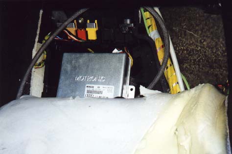
To clear engine fault codes in the AAN ECU, you can either disconnect the battery for 30 seconds (you will need the Radio code) or you can pull the ECU circuit breaker.
If you have accessed the ECU before, i.e. carpet is cut, etc. then you can clear the ECU codes by pulling the ECU circuit breaker (S64) for 30 seconds, in the red holder in the photo. (Photo courtesy of SJM Autotechnik (http://www.sjmautotechnik.com/troubl...ng/20vpin.html)
To remove the ECU from the car, try this link:
http://www.s-cars.org/postnuke/modul...rder=0&thold=0
If it doesn't work, you can find it via entering this in Google search window:
ECU removal site:www.s-cars.org (without the underscores_)
Last edited by UrS4boy; 08-22-2009 at 12:44 PM.
