Close Trunk With Remote Experiment


 05-27-2014, 12:41 PM
#12
AudiWorld Super User
Thread Starter
Any electronic relay - if you have frys electronics or radio shack (I don't know if they're still alive) - 12V is a must.
<a href="http://www.halted.com/commerce/catalog/spcategory.jsp?category_id=1154&czuid=140122247926 0">I get my stuff from here</a> if the part is not in my samples box. Choose the cheapest 12V relay will do.
Cheers,
Louis
<a href="http://www.halted.com/commerce/catalog/spcategory.jsp?category_id=1154&czuid=140122247926 0">I get my stuff from here</a> if the part is not in my samples box. Choose the cheapest 12V relay will do.
Cheers,
Louis
 05-27-2014, 03:51 PM
#14
AudiWorld Senior Member
 05-27-2014, 09:38 PM
#15
AudiWorld Member
Louis, how about a schematic for this awesome upgrade? Some of us need a bit more direction. While i can use a solder iron, shrink wrap, etc. would appreciate some details on how you wired the relay (where did you get power, etc) as well as details on the which relay pins go where?
Nice discovery, Thanks in advance!
Nice discovery, Thanks in advance!
05-27-2014, 10:37 PM
#16
AudiWorld Member
If I had to guess,
I would say the two pins on the latch green and brown are the relay coil,
Then the actual NO pins of the relay would be the two middle pins on the button for the trunk close plug.
The relay would energise when the remote activates the latch, and trick the car into thinking the button has been pressed (which normally joins those two pins closed by the relay)
Mike
05-28-2014, 06:57 AM
#18
AudiWorld Super User
Thread Starter
[QUOTE=Galco;24572590]Louis, how about a schematic for this awesome upgrade? Some of us need a bit more direction. While i can use a solder iron, shrink wrap, etc. would appreciate some details on how you wired the relay (where did you get power, etc) as well as details on the which relay pins go where?
-2 center pins of the close switch (rectangular black button) Green & Brown (pin 2-3) of 4 pins are shorted when you press the button - this will tell the system to close the trunk (only when the trunk is opened- how does it know that? pin #1).
-The latch pin 1 and 2 (Green and Brown) when remote or door activate, will produce a pulse of 12V between them and Green is Positive and Brown is Negative.

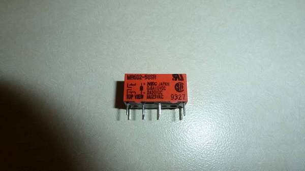
-A relay will have 2 inputs and 1 or 2 outputs
- 2 inputs are terminals of a coil (will have +/-) - when the potential between these inputs are at the designed voltage, it will close the output pins (which normally are open).
- The output pins are open when the coil is not energized (no potential difference between the coil) and closed when the input coil is energized.
Removed
Cheers,
Louis
-2 center pins of the close switch (rectangular black button) Green & Brown (pin 2-3) of 4 pins are shorted when you press the button - this will tell the system to close the trunk (only when the trunk is opened- how does it know that? pin #1).
-The latch pin 1 and 2 (Green and Brown) when remote or door activate, will produce a pulse of 12V between them and Green is Positive and Brown is Negative.
-A relay will have 2 inputs and 1 or 2 outputs
- 2 inputs are terminals of a coil (will have +/-) - when the potential between these inputs are at the designed voltage, it will close the output pins (which normally are open).
- The output pins are open when the coil is not energized (no potential difference between the coil) and closed when the input coil is energized.
Removed
Cheers,
Louis
Last edited by ltooz_a6_a8_q7; 05-28-2014 at 10:31 AM.
05-28-2014, 07:09 AM
#19
AudiWorld Wiseguy

This is a great mod. Anyone know what electrical plugs/connectors are used? I'd like to make a plug and play loom insert for this. Not a huge fan of splice connectors and electrical tape for permanent modifications. 
05-28-2014, 09:57 AM
#20
AudiWorld Super User
Thread Starter
If you trace these wires back, they're in the battery compartment. You can do them there, I think, if you do, please take pictures and share.
Cheers,
Louis